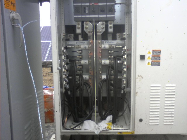
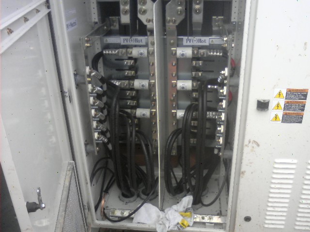
At each Inverter, I pulled the parallel 300 MCM conductors a bit longer than needed; bent them where I planned the Current Transducers to go; then cut, installed crimp terminations, and connected:
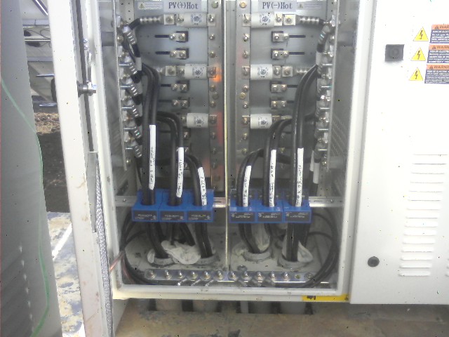
Next, I installed DIN Rail via angle brackets connected to the sides, slipped the CT’s over the “Hot” conductors, and snapped them onto the DIN Rail:
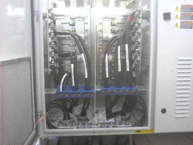
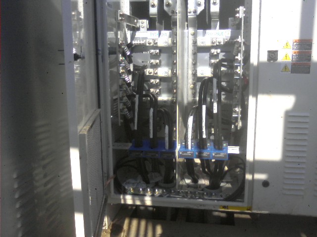
Later, I ran an 18/4 Shielded Cable to each CT, and connected it the Monitoring Equipment.