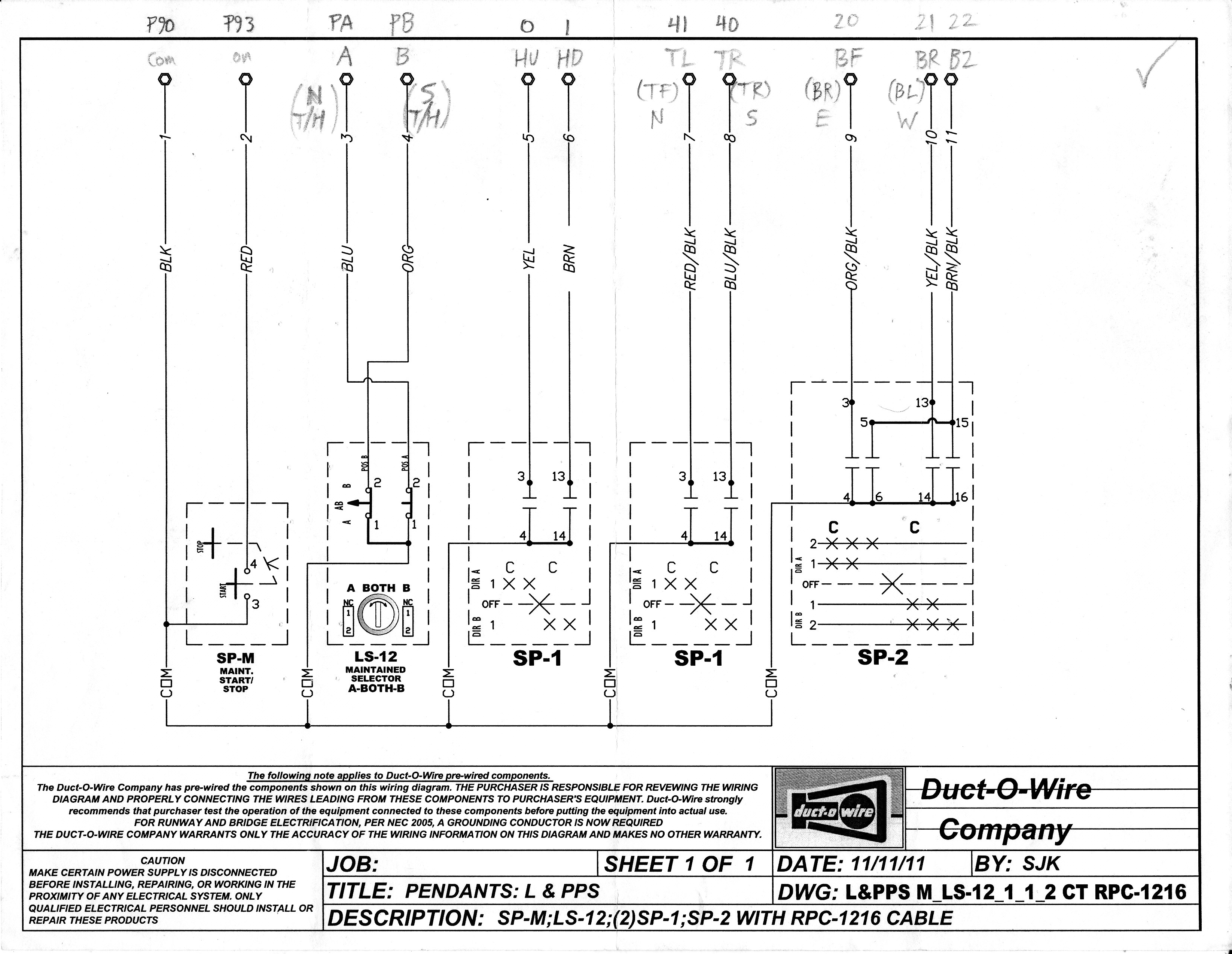
Here’s the manufacturer’s diagram for each of the Pendants to be installed. I didn’t want to change the Pendants‘ internal wiring – it would make it harder for troubleshooting & repair in the future. (On top, I wrote which control relays & terminals I would connect each wire to):
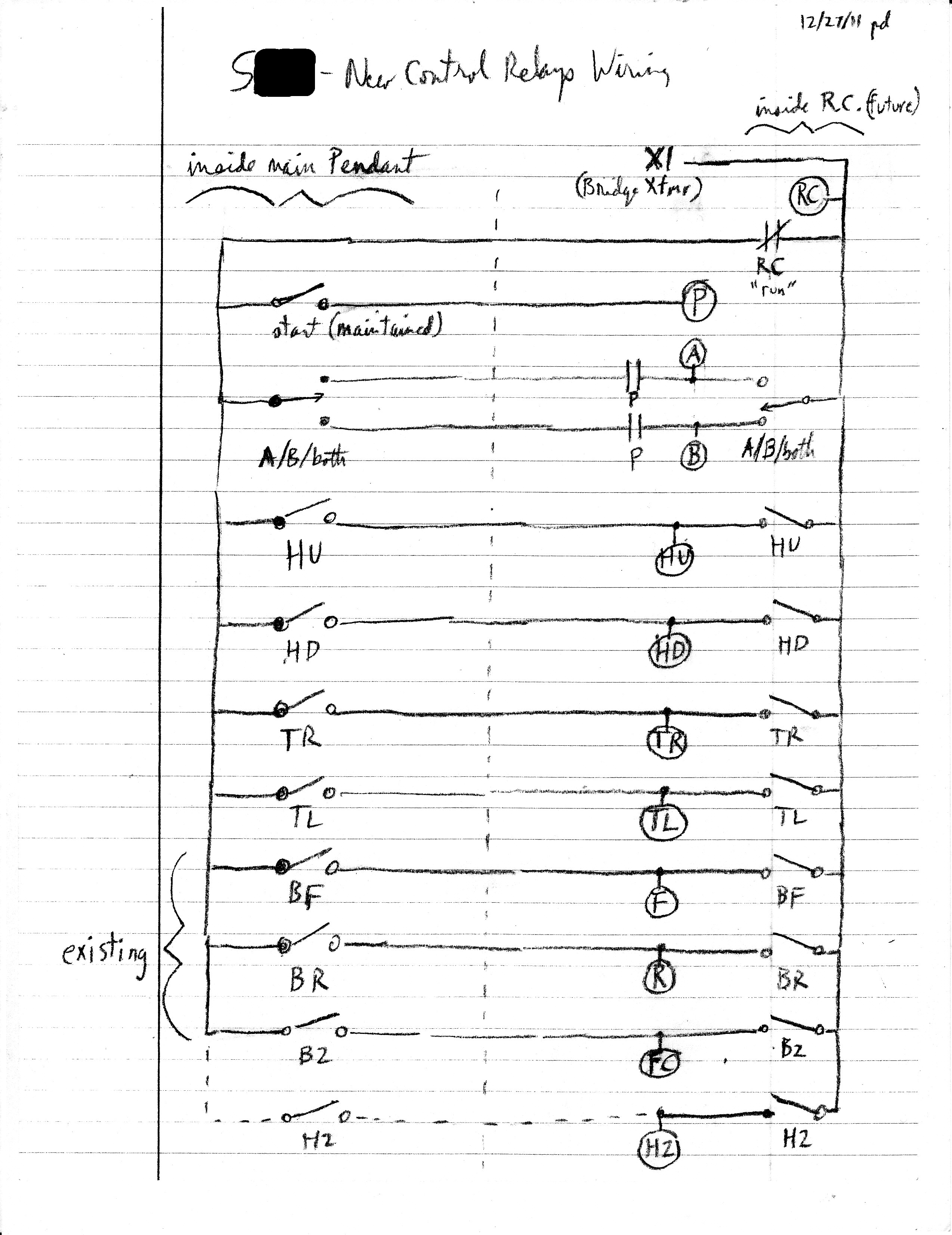
Here’s a preliminary diagram, showing how I planned to connect the Pendant and the Radio to new Control Relays:
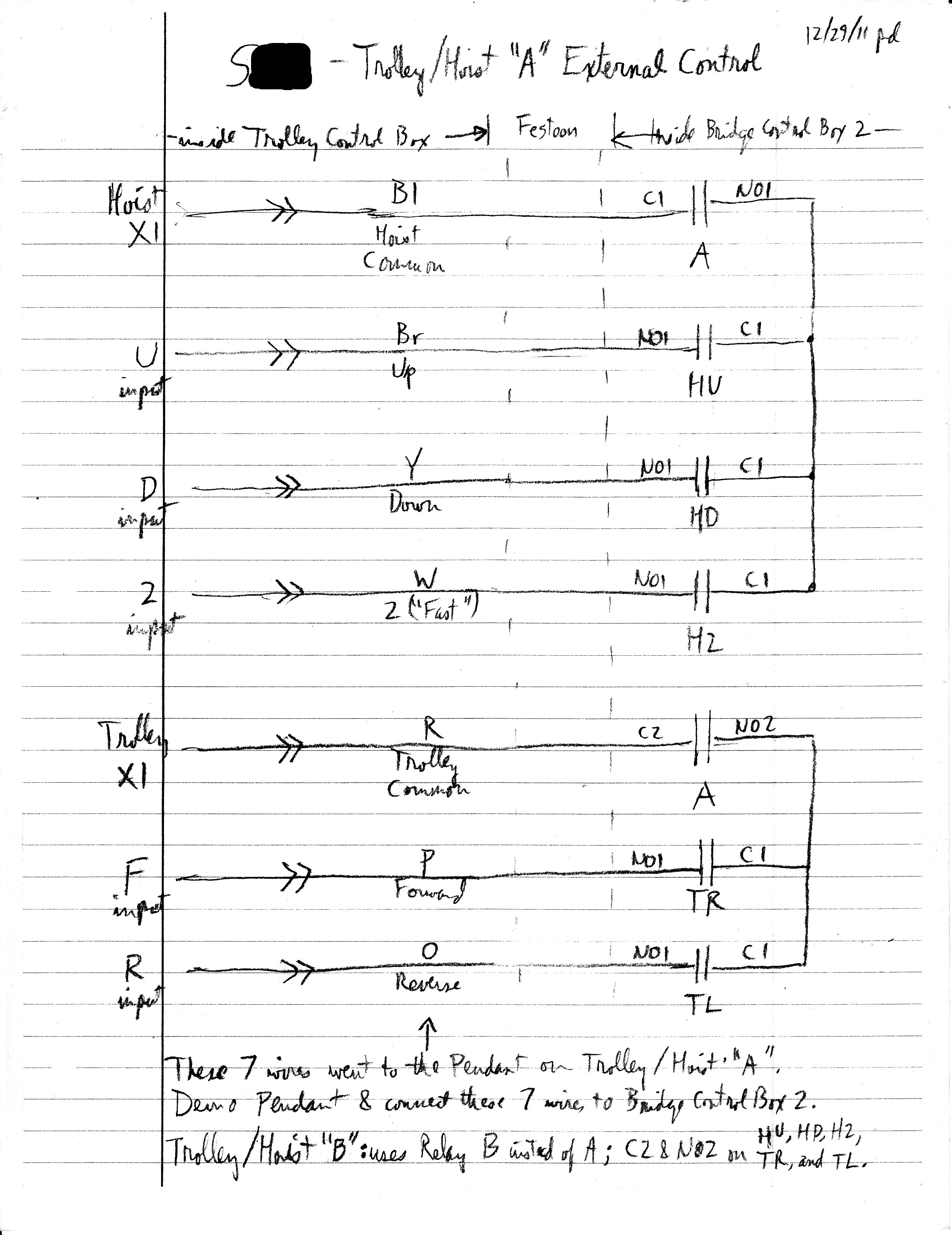
Here’s the control wiring & inputs for each Trolley / Hoist setup. On the left side are the “X1” control voltages and control inputs, as connected by the manufacturer to their original Pendant on each Trolley / Hoist combo. At the Trolley Junction Box, I replaced each Pendant with a Festoon Cable, and simply connected a Festoon conductor to where each original Pendant wire was connected. (I didn’t want to change the control wiring inside the Trolley Junction Box, to simplify future troubleshooting & repairs):
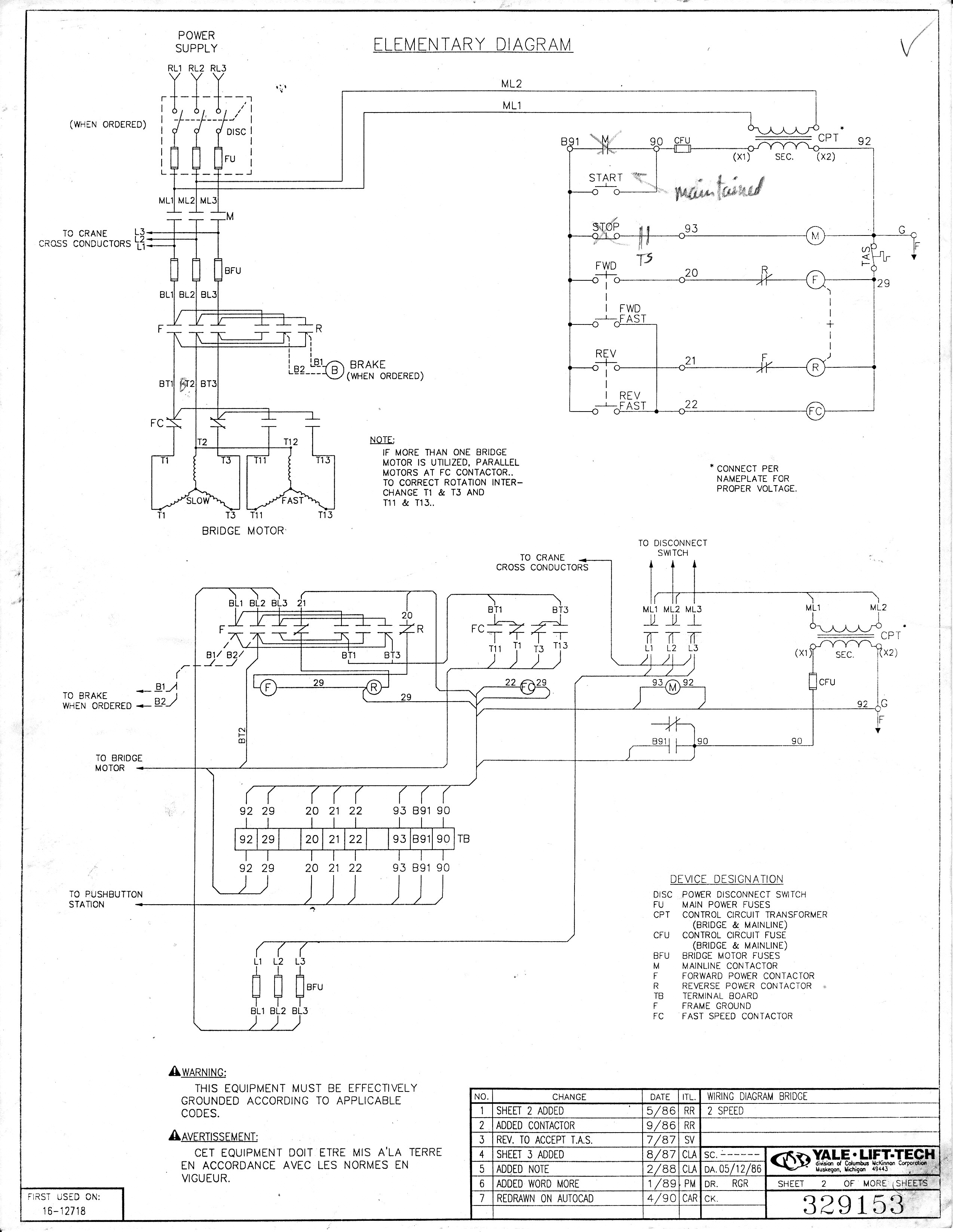
Here’s the manufacturer’s diagram for the Bridge (as modified – both Pendant and Radio had “Maintained” master Start / Stop contacts):
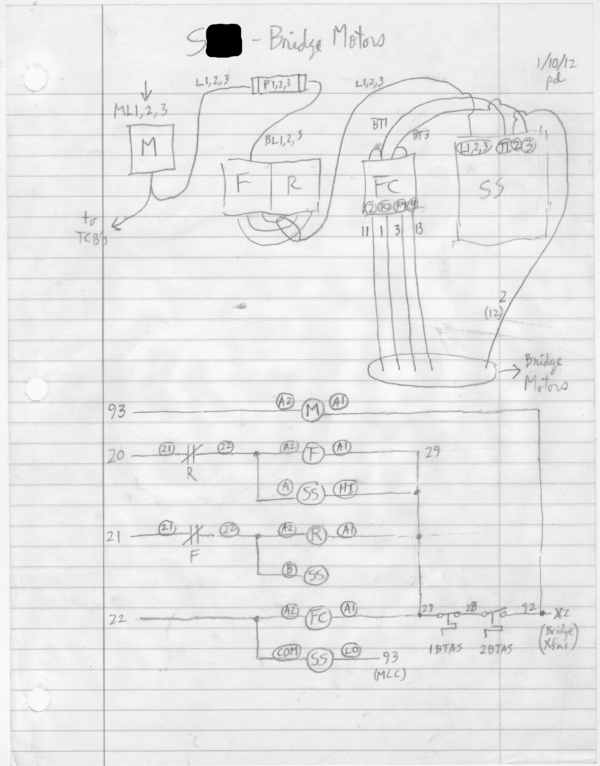
Here’s my diagram for how I connected the Bridge controls, including the “Soft Start”:
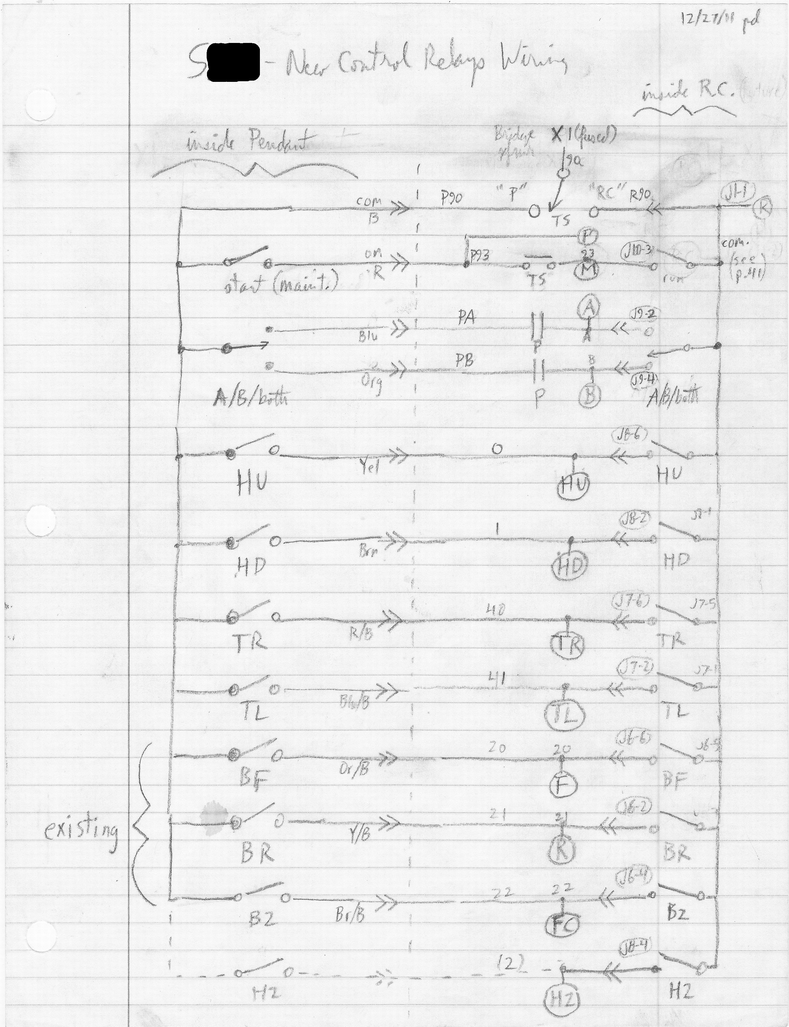
Here’s my final diagram for the Control Relays (including the wire labels, and the terminal numbers on the Terminal Blocks inside the Control Box and the Radio Receiver):