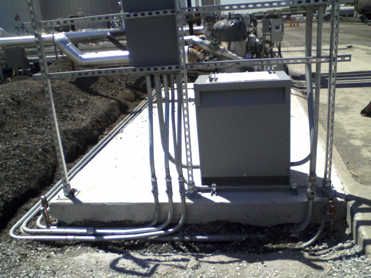
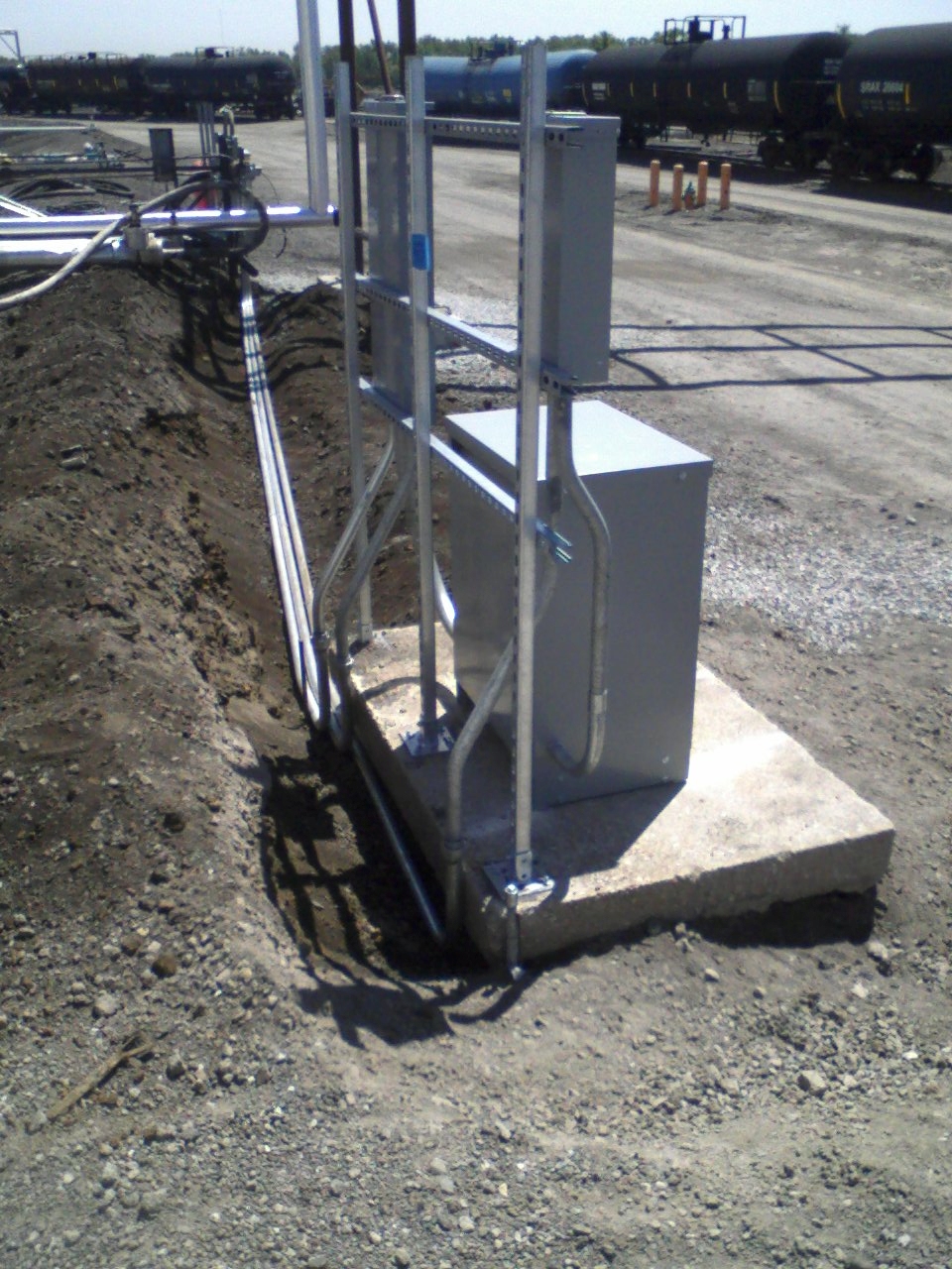
On a newly-poured concrete slab, I mounted a Unistrut rack; set the 75 kVA transformer, disconnect & 100-Amp panel; and did grounding for the derived system (2 ground rods and piping, as shown).
Bent, cut, threaded & ran the underground 1" & 1-1/4" HW conduit (1 for the 480V supply, 3 for 120/240V heat trace loads).
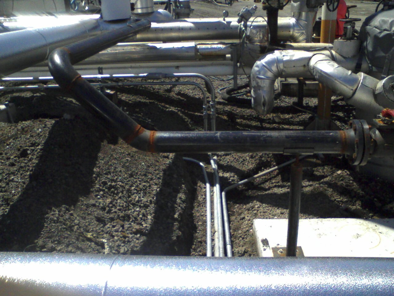
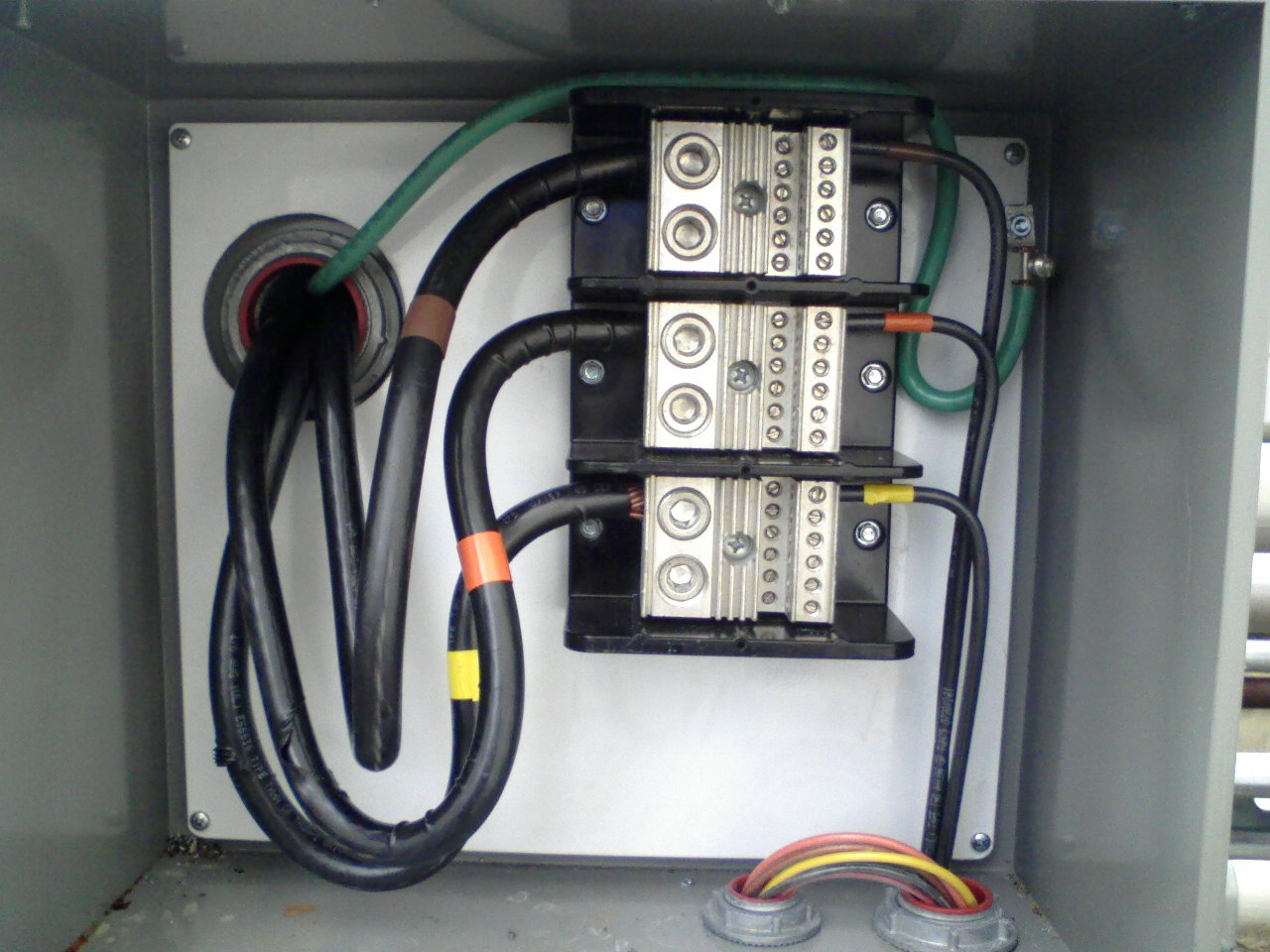
Connected the supply conduit to a new 24x24x8" junction box, and from there ran 300 feet of 2" HW conduit to tap into an existing junction box containing a 200-Amp feeder:
Ran conduit, installed thermostats, pulled circuits & connected the Heat Trace:
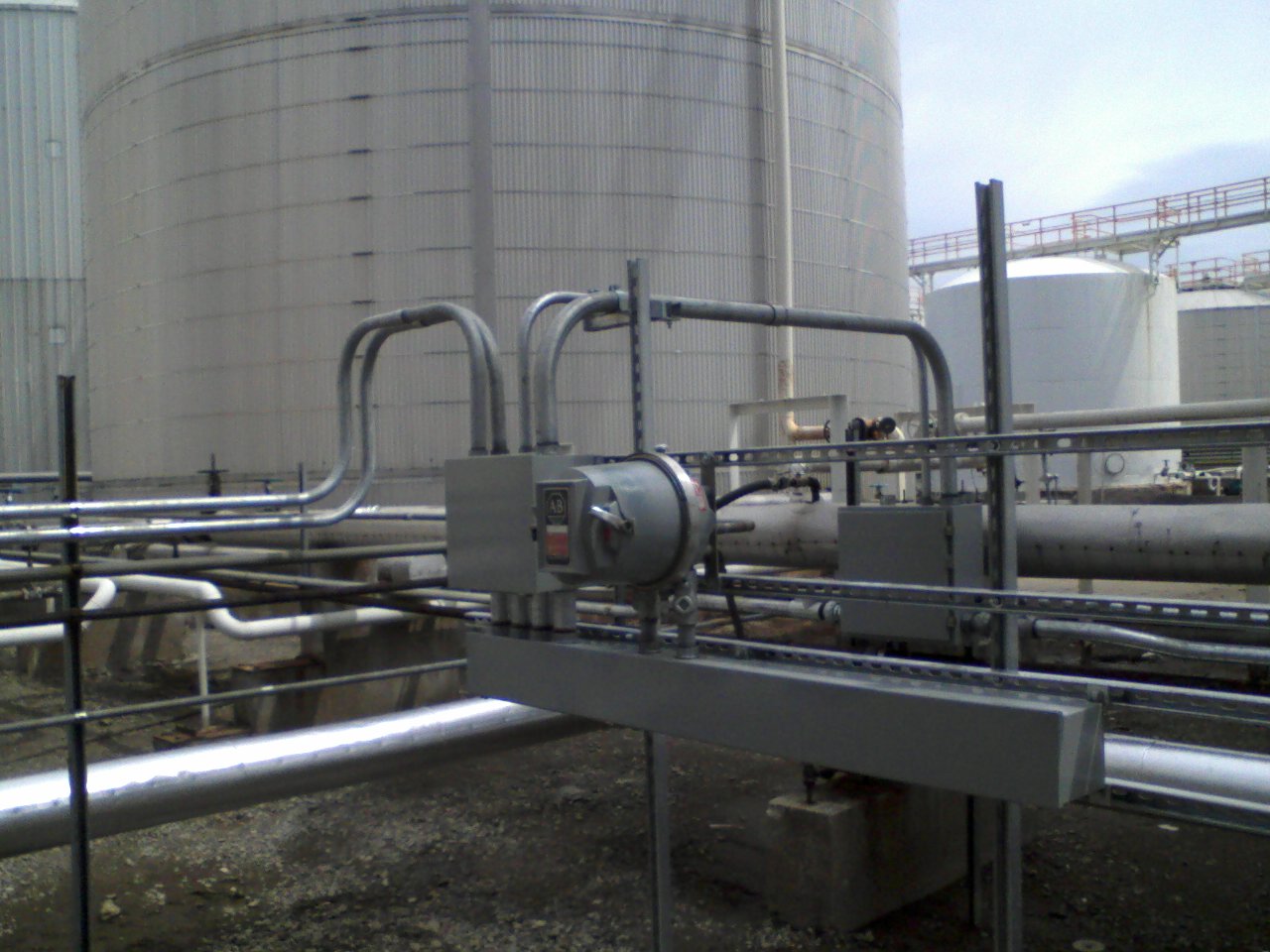
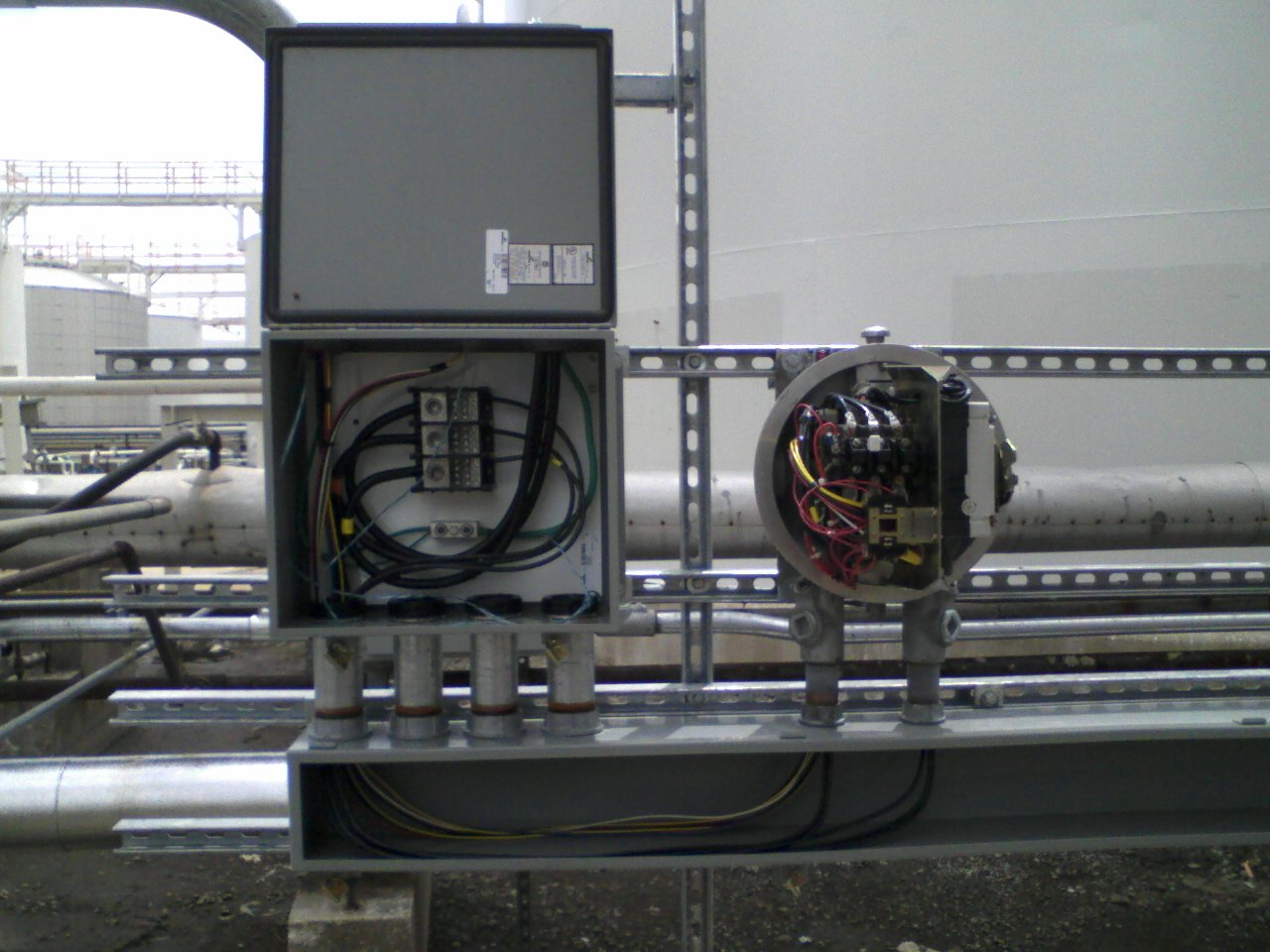
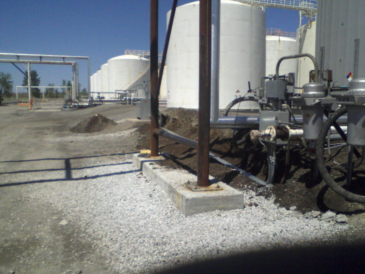
On a concrete pad they poured, I installed a Unistrut rack, a 15×18×8" junction box, a 8×8×72 gutter, and a 25 H.P. motor starter.
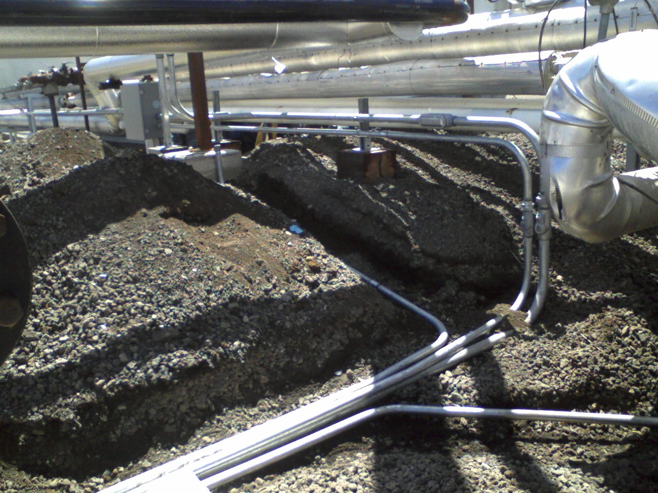
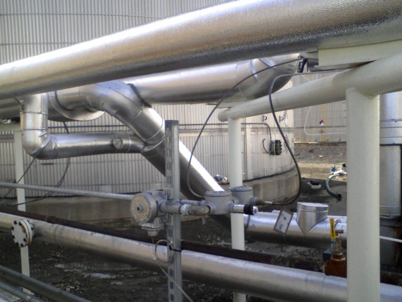
Bent, cut, threaded, and installed the supply conduits into the junction box (2" HW for 480V/200A power, 1-1/4" HW for the heat trace); and the 2 x 1-1/4" HW conduits out (1 for 480V motor leads, 1 for heat trace & control wiring):
Continued the two 1-1/4 HW conduit runs for the motor & heat trace.
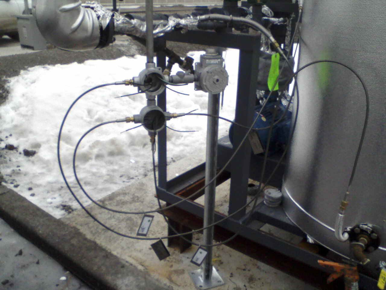
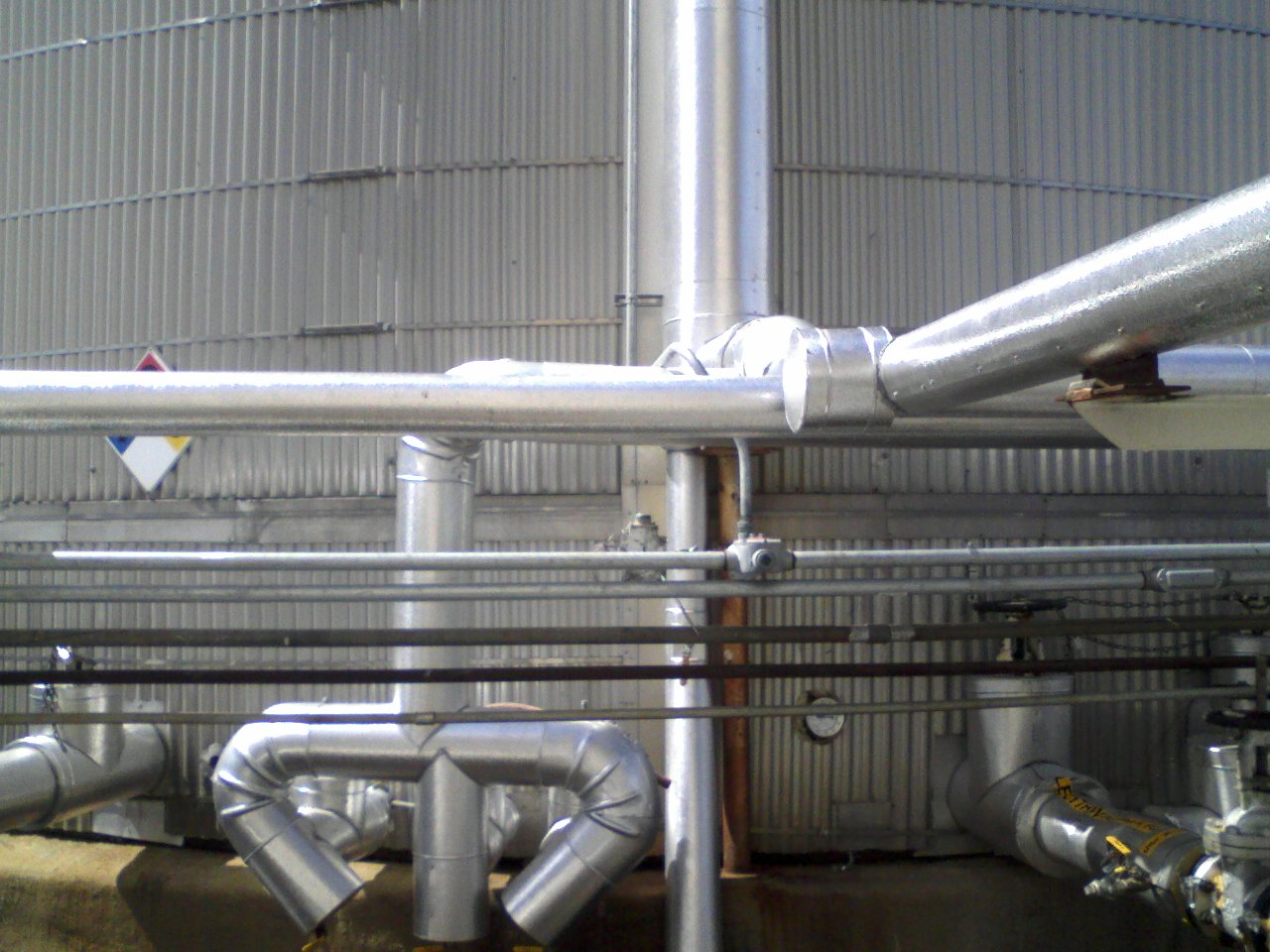
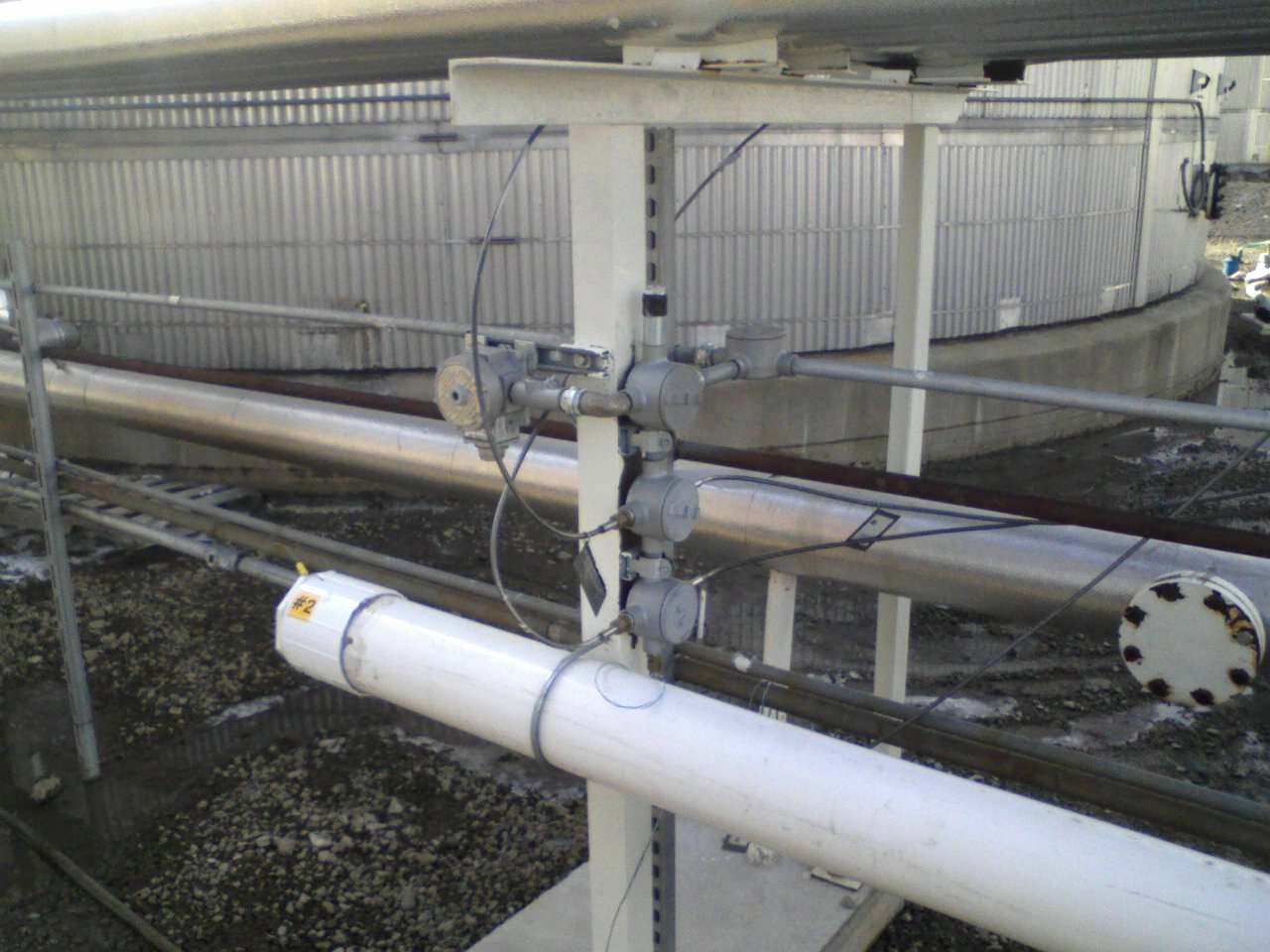
Did GRX's as needed for the thermostat & to the heat trace at the top of the tank:

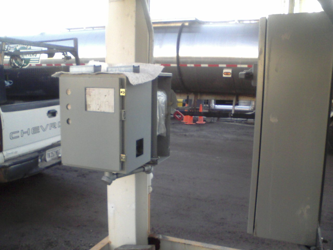
Stopped one 1-1/4" HW conduit at a new reversing switch, and ran new 1-1/4" conduits to the motor and VFD:
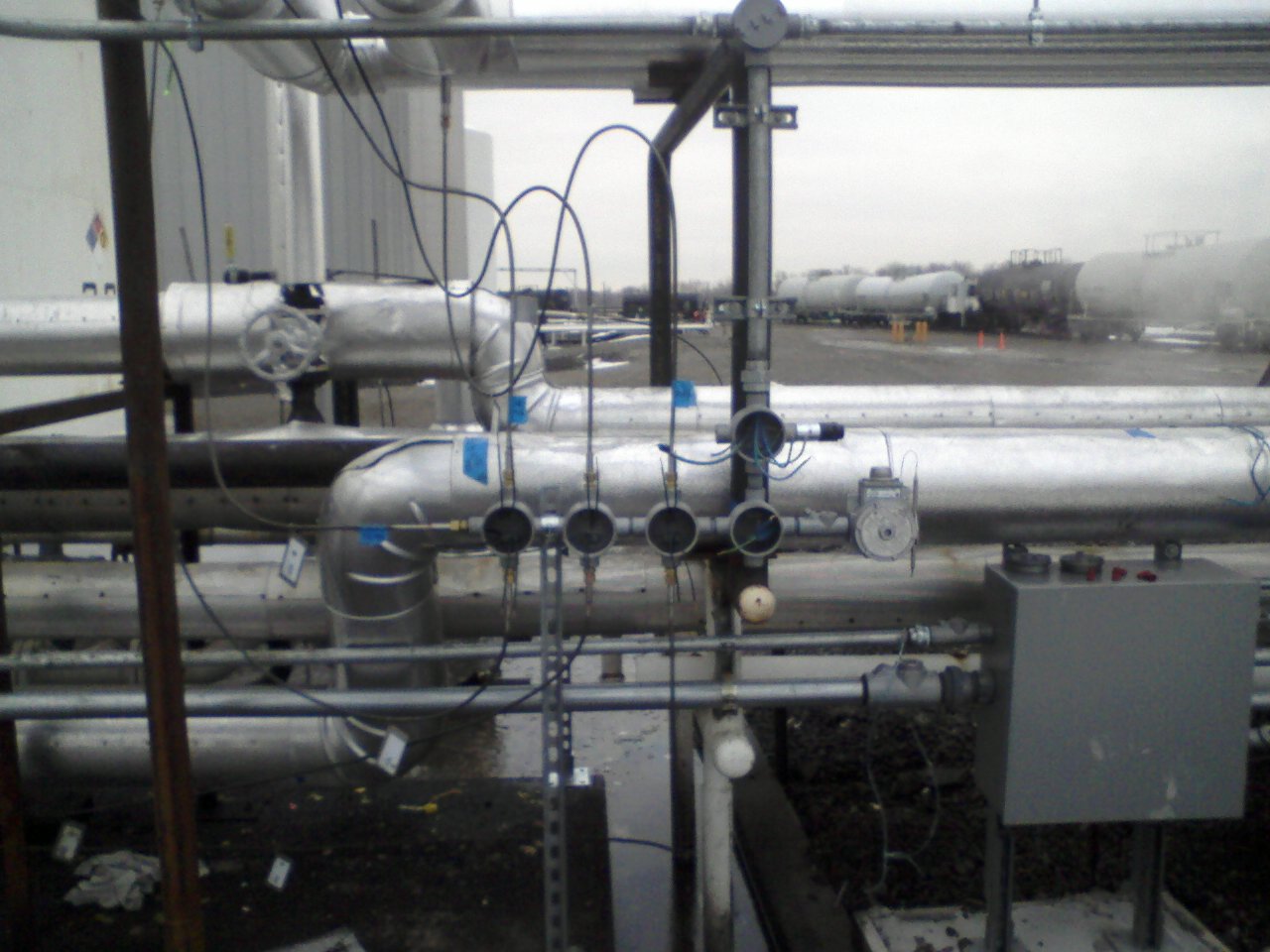
The second 1-1/4" HW conduit for heat trace ends at a 1-1/4" GRX (can be seen in the above picture). Installed 3/4" HW, GRX's, thermostats, etc. to connect to existing & new heat trace:
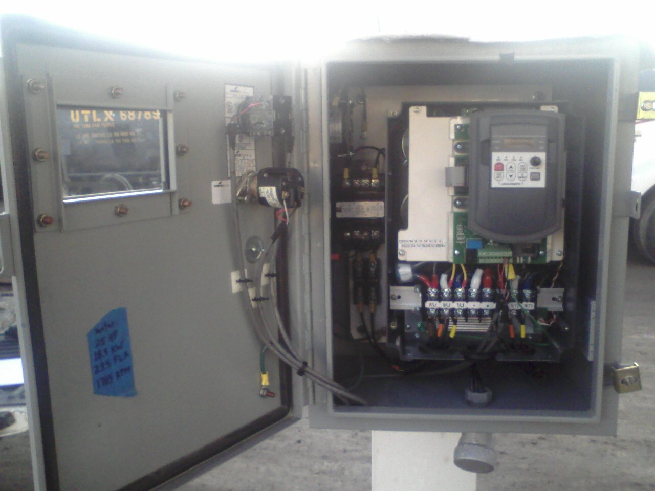
New VFD I installed for a 25 H.P. motor. First I had to redo the Unistrut rack, and move an existing starter a few inches to the right:
.jpg)
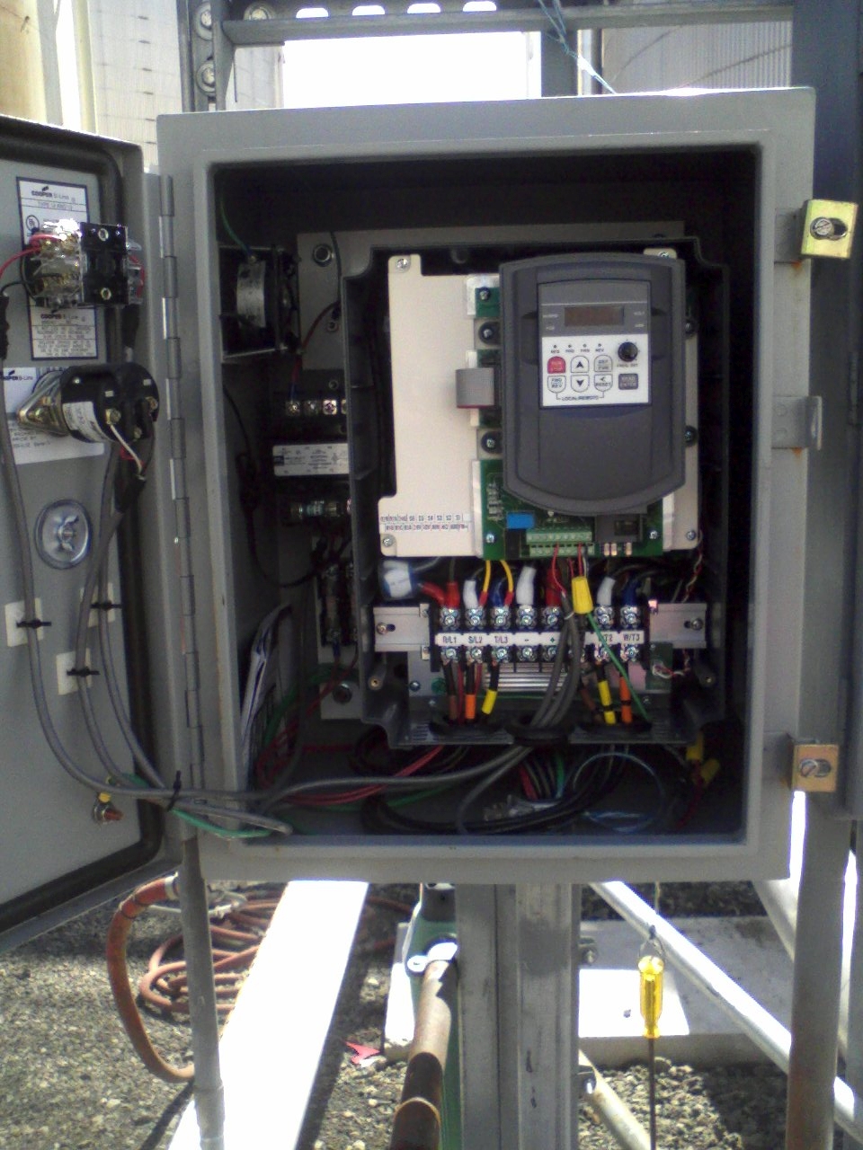
Wrote instructions for the Operators to use the VFD: (Can be seen in the above picture, hanging above the “Start / Stop”)
.jpg)
On a concrete slab we set in place with a skidsteer, I mounted a Unistrut rack, and set the 75 kVA transformer, disconnect & panels. Bent, cut, threaded & ran 1-1/4" HW conduit (1 for 480V supply, 2 for 120/240V heat trace loads):

The third VFD I installed:
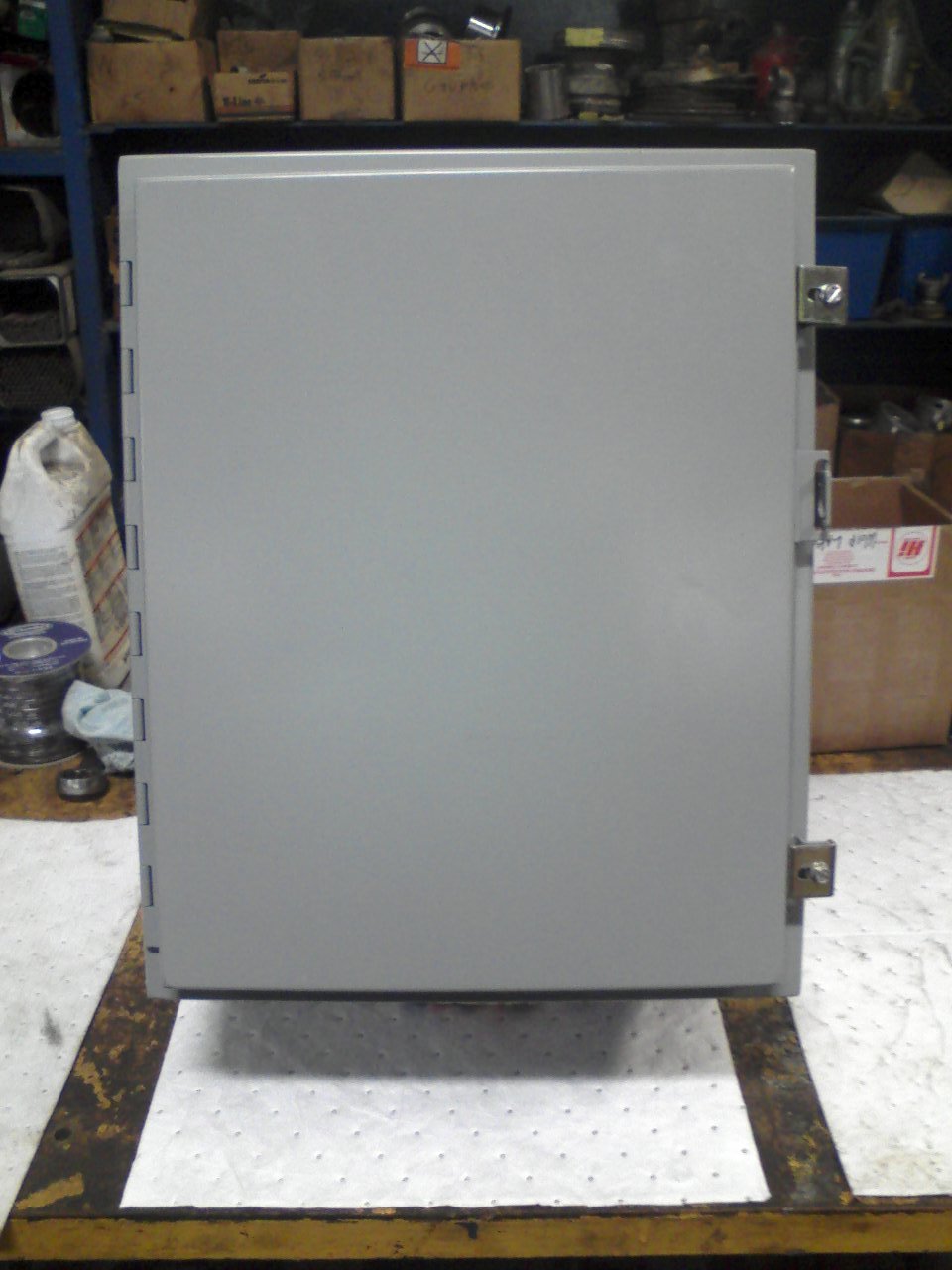
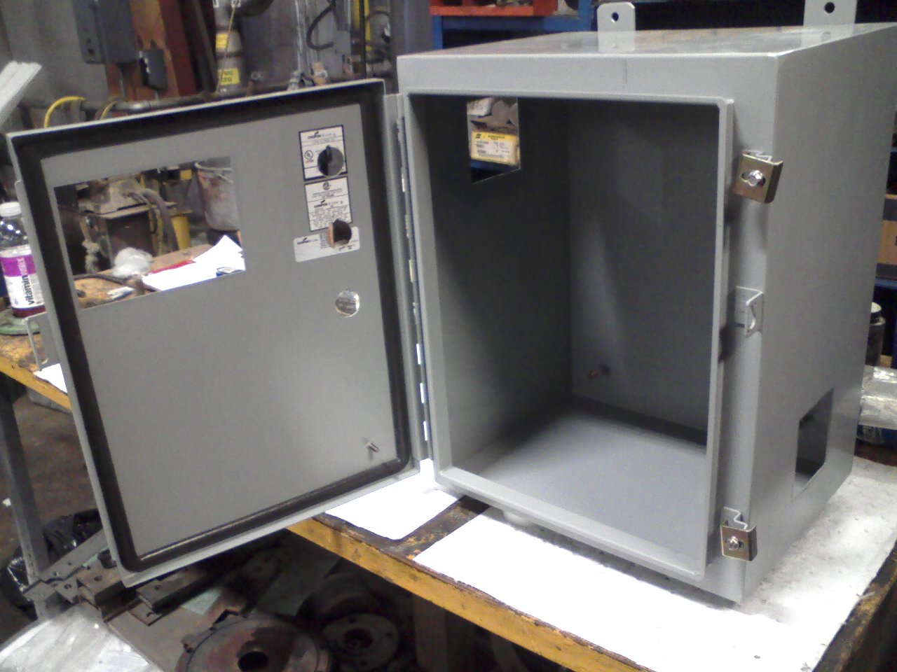
For each VFD I used a 15×12×10 “Nema 12” enclosure, sized to fit the VFD and its associated equipment.
With a Metabo, I cut the holes for the viewing window (to see the readout with the cover closed), and for a cooling fan (fan / exhaust on left, intake on right). Used a 3/4" KO punch for the control switches, and a die grinder to bump them up to 30mm:
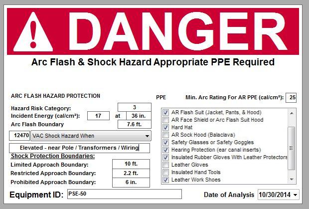
Did site-wide “Arc Flash” calculations as per NFPA 70E.
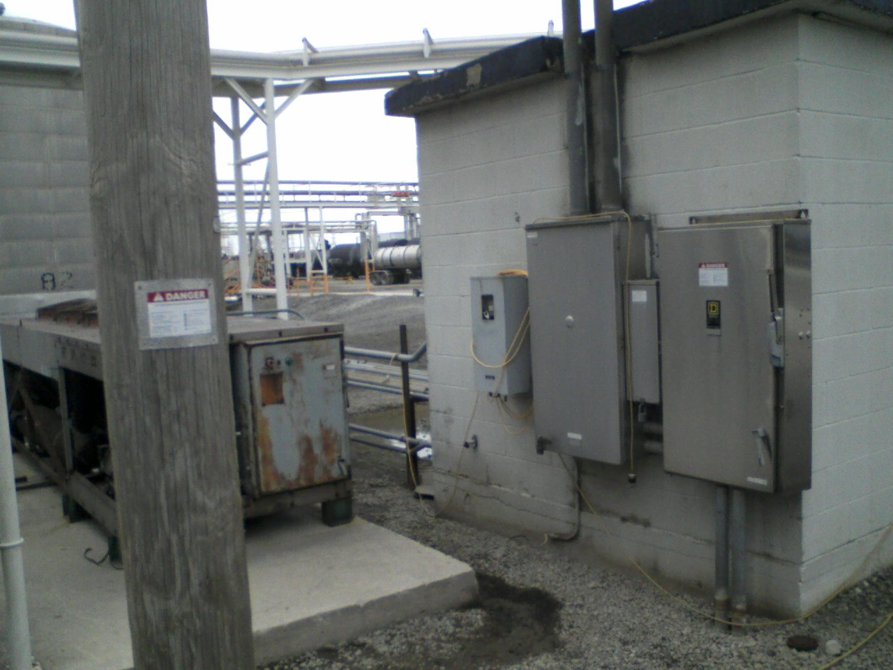
At all equipment required to be labeled, I installed NFPA 70E-compliant Arc Flash labels:
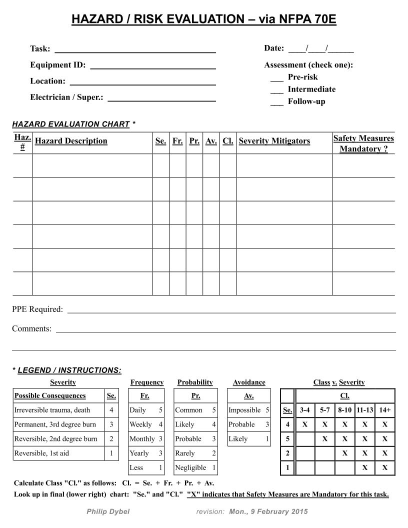
Did a preliminary NFPA 70E “Electrical Hazard Risk Assessment”, documented the results & submitted to management:
.jpg)