When I first arrived at the job, I saw that my company had installed two new “Over Head Single Girder” bridge cranes, onto runways running the length of the building. On each bridge girder was hung two electric chain hoists – each with an integral electric trolley, and each having its own factory-installed “Pendant” push-button control box hanging on a cord to floor level. On both ends of each bridge girder was a drive motor, mechanically connected to a drive gearbox.
The electrical work that had been done was: the power supply “Hot Rails” under the runway were finished, and the festoon cable support system and cables had been run on each bridge. None of the electrical boxes were mounted on the bridge girders; none of the cables were landed or connected.
The plan was to install a new control system for each crane: remove the existing Pendants from each Hoist / Trolley, and install a single new Pendant push-button station for each bridge: with two-speed controls for the bridge drive, and also for its two hoists & trolleys. Each Pendant would have an “A / B / both” switch, to run each hoist / trolley separately, or both together. Also a Radio Controller that would do the same thing as the Pendant. Also a “Soft Start” for each bridge drive. Then do power & control wiring as needed, and make it all work.
So that was my assigned task: “get all the electrical finished” – and that’s about all the details I was given. So I gathered what parts and manuals that were on site, drew up some diagrams, and this is what I came up with:
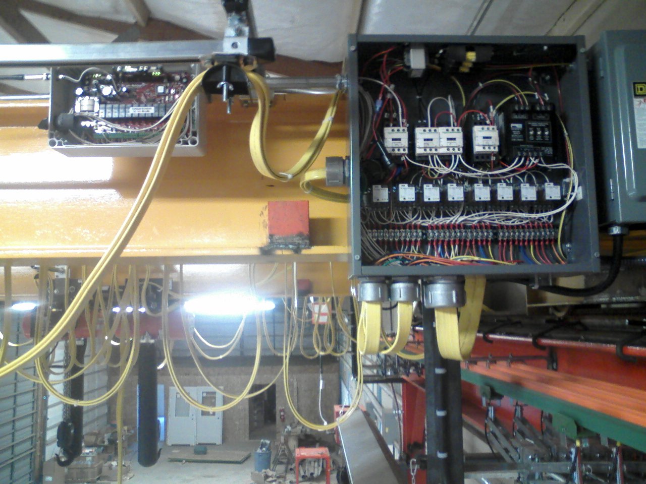
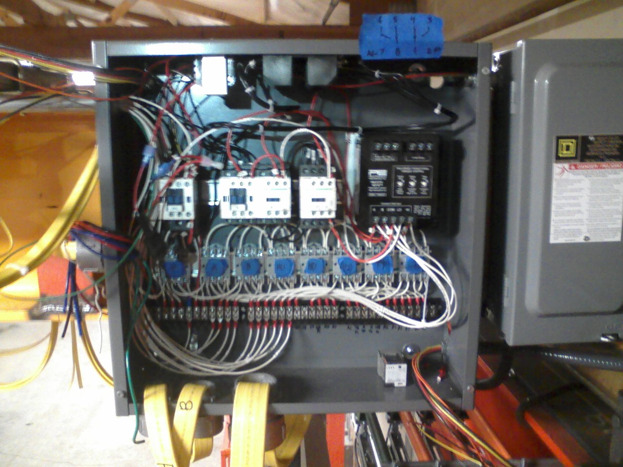
I started with an empty Control Box: got an 18 × 18 inch “Nema 1” enclosure, 6 inches deep. Punched holes as would be needed for the Power Supply, Festoon Cables, Motor Raceways, etc. Removed the Transformer, Fuse Block, and Contactors from the manufacturer-supplied bridge control box (10 × 12 × 4 inch - too small for everything I needed) and mounted them in the new box. Installed new “DIN Rail”, snapped in the Control Relay Sockets, and temporarily covered each with “Blue Tape” & labeled to indicate what function that plug-in relay would perform. Also mounted a “Soft Start” for the bridge motors, and new Terminal Blocks:

Next, I mounted the box on the bridge girder, and also the Disconnect and Radio Controller, and connected them with raceways. Attached the Festoon Cables (for the Pendant, and both Trolleys and Hoists). Ran conduit to each of the Bridge Motors and pulled conductors; connected the Power Supply (“Hot Rails”) to the Disconnect. Did all the internal Control Wiring between the Transformer, Contactors, Relay Sockets, Terminal Blocks, and Radio Controller:
Then I stripped back the Festoon Cables and connected the wires to the Terminal Blocks. Plugged the Control Relays into their Sockets, powered up and tested for correct operation. After that, connected the Power Subfeeds (“Cross Conductors”) to the Hoists / Trolleys and the Bridge Motors, and tested again:
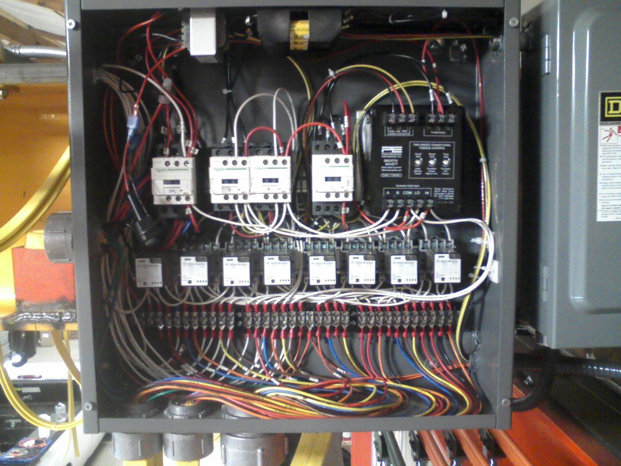
Here’s the finished product (with front covers off), where you can also see the Radio Controller, and the second crane in the background (I did that one identical to the first):